THRUST AND GUIDE BEARINGS
General Information
The turbine-generator unit presents remarkable masses under rotation and considerable inertia forces, that increase if masses are not balanced, come into play. The runner may be subject to lateral forces due to the asymmetric flow that strikes it and the generator may be subject to magnetic pull. These forces associated to the weight of the rotating parts must be controlled by means of the BEARINGS. In the case of HORIZONTAL machines, the main loads on the bearings are due to the weights that act in perpendicular with the machine shaft and the axial loads, also present, are smaller than those in the corresponding vertical unit because in this case there is no weight along the shaft. Making reference to a vertical unit, the axial loads are discharged by the THRUST BEARING and the radial ones by the GUIDE BEARINGS. The number of guide bearings depends on the type of turbine-generator unit and essentially by the length of the shaft line. A verification if the number adopted is correct is carried out by means of a calculation of the flexural critical speeds. The bearings may be oil, grease or water lubricated and, depending on the application, we can find sliding smooth (the most used) or rolling (rollers, balls) surfaces.
GUIDE BEARINGS
In HORIZONTAL UNITS, the definition of guide maybe improper because they counteract also the weight of rotating parts. Anyway, once made this clarification, we can say that, depending on their behavior, in this type of machines we can identify two main types of bearings: STIFF and TILTING. The stiff ones are used if there is no appreciable deformation of the shaft line, while the tilting ones may self-align making use of spherical seats (fig. 1). Very often they are combined with the thrust bearing. The (fig. 2) illustrates one combined bearing with two opposite counterthrusts that prevent the axial sliding in both directions. Depending on the specific pressure on active parts and on the rotation speed of the shaft, the lubrication may be forced, by the aid of pumps, or inside the tank itself by using rings placed on the shaft that are dragged in rotation by the shaft itself. Their use is limited in first approximation to the following values of the peripheral speed U of the shaft: 2,5 m/s <U< 13 m/s out of this interval it is necessary to carry out the forced lubrication. Indicating by D the shaft diameter, the length of the active part of the bearing is on average L= (0,8 ÷ 1)
In VERTICAL UNITS, the main function is to keep the shaft aligned vertically and support any radial force that can take place during the operation. The tilting guide pads (fig. 3.1 and 3.2) are usually adopted, even if we can find bearing with bushings in case of mean-small units. The lubrication may be natural with a thermal exchange coil placed inside the tank or forced by the aid of pumps and external exchangers. In general the use of this type of bearings requires the presence of a manifold, integral or placed on the shaft and, according to the dimension of the machine the number of pads may vary from 6, 8, 10, 12, …. The lining materials that can be used of the bearings are very different: rubber, bronze, resin, white metal, the last one is the most used one. An example may be SnSb8Cu7 UNI 4515 that presents in room temperature a hardness BRINNEL of 23÷27 MPa.
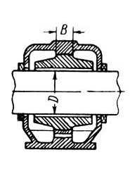
Fig 1
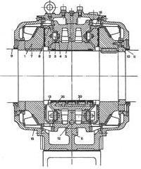
Fig 2
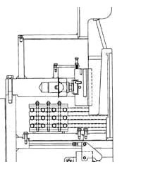
Fig 3.1
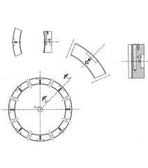
Fig 3.2
THRUST BEARINGS
In general, in vertical machines, the thrust bearings are positioned above the generator and often they are combined with one guide bearing (fig. 4). Very important is the resting point of each pad with respect to the load barycenter. In monodirectional machines, the position of the resting point is not barycentric and this favors the formation of an oil film between pad and thrust runner. In reversible turbines (pump-turbines) the resting point must be located halfway of the pad length and therefore this will cause a more critical situation with respect to the monodirectional machines. As a general dimensioning criterion, we keep a specific pressure on the pad surface of 2,5÷4 MPa, (areaching even 6 MPa) depending on the material used. For what concerns the lubrication and the cooling system, it is valid what already said for vertical guide bearings. Generally, the maximum temperature measured on the pads does not exceed 80°C and that of the oil bath in which they are submerged 50÷60 °C. We can summarize 3 main aspects for a good operation of a thrust bearing:
1) limited specific pressure on the pad
2) homogeneous and generous cooling
3)surfaces in relative motion (pad and thrust runner) machined with narrow tolerances
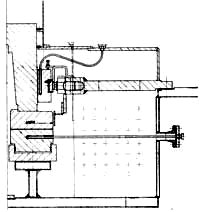
Fig 4
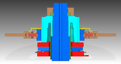
Fig 4bis
Figure (fig 4 bis) represents the section of recent combined bearing installed in a plant of medium power.
The (Fig. 5) shows the construction drawing of a typical thrust pada
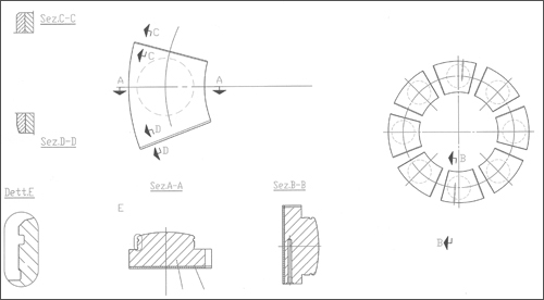
Fig 5
OIL INJECTION
The oil injection is more and more used between pad and thrust runner. The purpose is to separate the surfaces in touch in order to prevent the sliding at the moment of start up. This happens more easily after many days of stop of the machine because the surfaces in touch have the tendency to paste. The injection pressure must be such to generate a load that exceeds the rotating parts and causing in this way the detachment between thrust pads and rotating parts. All pads, or only some of them, may be equipped with a pocket for the injection (fig. 6, 7). Obviously the dimension of the pocket depends on the dimensions of the pad and of the load to lift up and must not be an obstacle for the formation of the oil film. Just for reference and in first approximation, the oil pressure could be of about 120 bar. The injection takes place before the turbine begins to move and it is a normal practice to disable it when the rotations reach about 90% of rated speed. During the stop phase, it is also usual to introduce the injection at about 90% of rated speed and to exclude it when the machine is completely stopped.
If we consider a circular pad, the diagram of (fig. 7) shows how the oil acts between the two surfaces and the values of discharge and pressure of the pump.
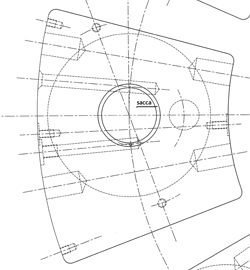
Fig 6
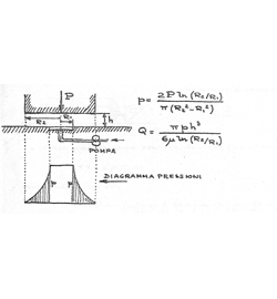
Fig 7
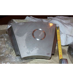
Fig 8
HYDROSTATIC BEARINGS
In general hydrostatic bearings are used mostly when the relative velocity between fixed and movable parts is low, as for example in telescopes. High relative speeds imply more entrainment of the oil or of any fluid passing through the fixed and the rotating parts, increasing in this way the power employed. Here below there are some considerations of general nature, made without entering into details that would render too heavy the subject matter, and anyway remaining inside the area concerning the applications for hydroelectric units. Differently from the traditional hydrodynamic bearings, where the oil film is granted by the relative speed between pad and rotating part, in hydrostatic bearings the oil film between the surfaces in relative motion is assured by a source under pressure, usually pumps. Generally, this lubrication procedure gives the following advantages:
- very low frictions
- separation of the surfaces to be lubricated made in safety
- high stiffness of the oil film, often higher than that in the mechanical structures
The negative aspect is connected to the fact that the set up is more complex, as it can be deduced in the following description. The oil supply can be made under constant pressure or at constant flow. This means that in the first case the load variations on the bearing will cause variations of the oil film and then of the oil flow through the pad, vice versa in the second case the variable becomes the pressure because the flow is constant, that is to say that film variations due to load variations will imply a variation of the pressure generated by the feeding pump. We refer to Fig. (9) and indicate with:
pa = feeding pressure
p = operating pressure
Ra = feeding resistance
R = resistance supplied by the pad
P = Load on the pad
Q = oil flow

Fig 9
Given the value of load P and pad dimensions, we may consider with good approximation the operating pressure p=P/Aeff where the denominator term represents the effective area that is the area defined by the average line of the edges, indicated in the figure by means of brushstrokes and of perimeter L.
We consider now what happens in the circuit in case of constant pressure feeding
If we increase the load on the pad, the film height ‘ h ‘ decreases and on the contrary it increases if the load decreases. The pad resistance will then changes depending on the load, as we can also see in the resistance expression:
R =  ( v. fig. 9)
 = Dynamic viscosity
 p = Pressure head astride the pad
Therefore if P increases h decreases and R increases. The total circuit resistance given by R+Ra is bigger and since the feeding pressure ‘pa’ is steady, the delivery through Ra decreases as well, and the pressure ‘p’ under the pad will increase in order to compensate the overload. It is natural to underline that the pressure Pa has to be higher than the pressure that can be generated under the worst operating conditions. From a practical point of view, the feeding resistance can be realized by using a reducing orifice or capillary pipes. It is considered appropriate to have an oil film thicker for about 10 times than the maximum superficial roughness of the bearing surfaces. For what concerns the cavity of the pad, in order not to influence the oil motion and to keep the pressure constant, it must be at least 50-100 times higher than the film.
We consider now the feeding at constant delivery
From a general point of view, each pad shall be fed by a pump without the interposition of any regulation or control device. In this way we will have the pressures diversified from one pad to the other one and the film thickness will remain stiff. The pad acts as a viscous throttling device placed on the pump delivery and thanks to its height it regulate the delivery pressure. A decrease of the film height, due to an increase of the load acting on the pad, will generate an increase of the pressure inside the circuit, and vice versa an increase of the oil film, reducing in this way the R resistance of the pad, will cause a pressure decrease. In practice, to obtain a constant delivery source it is necessary:
- to use single pumps
- to use flow regulators
Flow regulators can be easily found on the market and their installation is obviously simpler than that of pumps. Here below the formula, very simple, that defines the stiffness in case of constant flow:

On the contrary the expression relating to the pad feeding at constant pressure is quite more complicated and moreover it depends on the ratio Ra/R (feeding resistance and pad resistance). In case of use of hydrostatic bearings in the hydroelectric field, it is necessary not to forget the high speeds of sliding between runner and pads. This implies the necessity to keep into consideration the increase of delivery to be supplied to the pads because of the removal of oil made by the runner itself. The film thickness, in case of hydrodynamic pads depends on the relative runner/pad speed and on the oil viscosity. In case of hydrostatic feeding, the film thickness doesn’t depend on the viscosity and, theoretically and in extreme case, there is no prohibition to use water as fluid.
The runner/pad relative speed has anyway the tendency to make the pad tilting due to the hydrodynamic effect, and this is the reason why the supporting area is generally partialized Fig. (10) in order to prevent the fluid from outgoing from the pad in a not uniform way. Because of the hydrostatic pad surface design, the resulting slope is much smaller than the one corresponding to the hydrodynamic one.

Fig 10
Here below a table comparing the characteristic values of a traditional bearing installed on one 40 MW turbine as well as the corresponding values, merely theoretical, when using a hydrostatic bearing. Obviously, the power generated by the bearing affects negatively the global efficiency of the machine.
| Description | Hydrodynamic | Hydrostatic |
|---|---|---|
| Bearing load (KN) | 1668 | 1668 |
| Rotation speed (Rpm) | 500 | 500 |
| Pads number | 8 | 8 |
| Shape of pad | trapezoidal | circular |
| Pads lining material | white metal | bronze |
| Pads baricentric diameter (m) | 0,89 | 0,9 |
| Metal pad area (m^2) | 0,068 | 0,022 |
| Average rate pressure on pad (Kg/cm^2) | 31,25 | 96,5 |
| Oil type | ISOVG 46 | ISOVG 22 |
| Pads average operating temperature (°C ) | 60 | 55 |
| Oil viscosity at operating temperature ( cSt ) | 16,42 | 12,75 |
| Friction coefficient | 0,00276 | 0,0006094 |
| Total oil supply for pads ( lt/min) | oil tank | 287,8 |
| Supply pump pressure ( Kg/cm^2 ) | 63,2 | |
| Supply pressure/operating pressure ratio | 2 | |
| Calories developed / absorbed at full capacity ( Cal/s ) | 25,6 | 13,37 |
| Calories developed / absorbed at full capacity ( Kw) | 107,2 | 55,9 |
| Oil film min height between pad and rotating part ( mm ) | 0,044 | 0,045 |
GUIDE BEARING
Again speaking of hydraulic turbines, it is possible to employ the hydrostatic bearings, at least from a theoretical point of view, on condition that appropriate precautions are taken. As it is well known, when using either the guide bearing with pads or those with bushings, the radial difference between the inner diameter of the pad and that of the shaft is certainly higher than a tenth of a illimeter, and even more, depending on the dimensions. It must be understood that this gap is too important for a hydrostatic bearing because it would imply the use of an excessive quantity of oil and a very low stiffness. One solution that can be adopted is to create a load outside the pad by using, for example, the Belleville springs. In this way the pressure of the injected oil will create the quantity of oil film deemed necessary, anyway amounting only to few tens of microns.