Pelton
Probably the Pelton (Lester Allan Pelton l’inventore) turbine is the only impulse turbine universally used nowadays. In (fig. 1) there is a schematized Pelton bucket with highlighted the most important geometrical quantities. Particular attention has to be put on the opening E at the bucket end, in correspondence to the external diameter of the same, which width shall be slightly bigger than that of nozzle diameter. This opening has the double purpose to allow the jet to operate for a longer time on the bucket without it is disturbed by the arrival of the following bucket.
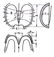
fig. 1
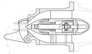
fig. 2 Injector
The edges of the opening must be particularly sharpened in order to limit as much as possible the unavoidable water sprays to any direction when they enter in touch with the jet.
These sprays are to the detriment of the efficiency and of the regular operation of the machine. The speed of the water that comes from the nozzle and then strikes the bucket is:  [1]
[1]
One of the most significant values for dimensioning one Pelton wheel is the peripheral speed coefficient that is defined by K=U/V [2] where as usual U is the peripheral speed of the wheel calculated on the pitch diameter D of the nozzle (fig. 3). The maximum value K can assume is 0.485 (to demonstrate this value is beyond the purpose of this site). Anyway, the values usually adopted may vary from 0.45 to 0.485 (see example)
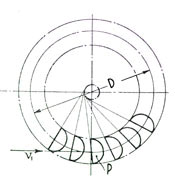
fig 3 Pitch diameter

fig 4
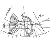
fig 5 Relative nozzle
D/d Ratio and number of nozzles
Said d the diameter of the jet coming out from the nozzle (fig.2) and as usual Q the discharge, we can write for a single jet turbine  or
or  [3]
[3]
For obvious reasons (fig. 3) it is clear that the ratio D/d cannot reach too small values. In general the limit adopted is D/d>7 even if in extreme conditions it is possible to go down to smaller values. The ratio D/d is modified by increasing the number of nozzles because the discharge shall be subdivided among them and then the diameter of nozzle d will decrease.
Deflector
Pelton turbines, besides the needles that are controlled by the governor that fixes the opening in accordance with the power requested at the moment, have a device called deflector (fig 6 and 7) that has the main task to deflect the jet in a very short time, 1÷2 seconds in case there is a load rejection. The deflected jet does not act any more on the wheel and allows the machine to remain within a limited number of revolutions and in this way the unit shall not be brought to runaway speed, generally 1.8 times the rated speed with remarkable stress for the devices under operation, because of lack of resisting torque with respect to the motor torque, and this gives rise to remarkable stress on the rotation devices.
fig 6
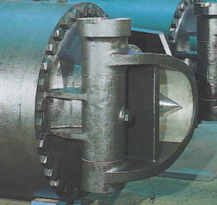
fig 7
Dimensions of Pelton wheel buckets
Dimension B (fig. 1) may assume on average the value B = (2.8 ÷ 3.5)d depending on the different manufacturers. For nozzles exceeding 200 mm we shall adopt values smaller than B while for d<20 mm we can adopt B= (4 ÷ 5)d. Making reference again to (fig. 1), we can assume:
A= (0,8 ÷ 0,9)B; C= (0,25 ÷ 0,3)B; E=d+(10 ÷ 40)
Angle  is generally included between 20°÷30°. The outlet angle
  will have great importance because it directly affects the outlet absolute speed V2, (fig 4)that we will try to render as small as possible in order to decrease the percentage of lost drop due to it, that is
Another not less important bond this angle shall have to respect is given by the fact that the water going out from one bucket must not hit the front bucket back because it would cause disastrous effects much more serious than the recovery of minimization which value for the average thread may be considered = 9°÷12°
Relative Jet
The whole of trajectories according which an observer integral with the bucket sees the jet moving is defined Relative Jet. The possibility to plot the relative jet allows us to determine the pitch between the buckets and consequently their number, preventing the jet to interfere on the following bucket before its action is exhausted and then preventing also that the pitch remains too big leaving the buckets inactive. The jet, rectilinear with respect to a fixed reference system, becomes curved seen by an observer integral with the bucket and in (fig. 5) we can see that the inner thread, that is as close as possible to the wheel center, laps the following bucket without interference.
Nozzle
We define Nozzle (fig.2) the component of Pelton turbine that sends the water jet on the bucket. It has the same function of Francis and Kaplan distributor and for this reason often it is called Distributor or simply Jet. Depending on size, it can have the servomotor inside as just showed (fig.2) and (fig.17) or outside for the small dimension of Nozzle or for constructive chosen (fig.20).
It is usual, as operative fluid, to use pressurized oil acting on the servomotor to move the needle. Then a set of springs provide the closing. The fig.19 shows a study of Nozzle without oil but only water. The purpose is to avoid pollution due to damages and wears. Following a brief description:
The channel (1) controls eventual leakages of water due to wear of seals on the shaft (A). The shaft is continuously in movement to adjust the flow and for opening and closing production. The same channel points out eventual leakages coming from the clean water acting on the piston. The clean water is injected in the “opening “chamber of the piston by means of channel (2). This channel is controlled by electrical valve and discharge also the pressured water; consequently the springs close the needle. The channel indicated with the number (3) is utilized to discharge the air and highlight leakage across the seals of the piston. At the end, the channel (4), is utilized for the passage of the LVDT cable in order to control the positioning of the needle managed directly by the electronic governor. Utilizing water, as motor fluid, particular attention is necessary on the material selection where components are subject to brush. For instance, one of possible solution, is to utilize ceramic lining and stainless steel.
Example of calculation of one Pelton bucket
Given: H= 500 m Q= 4 m3/s n= 500 rpm
from [1] V= 88 m/s and adopting K= 0,48 from [2] U= 47,5 m/s Rrmembering that  we obtain the pitch diameter D= 1810 mm (fig 3). Dalla [3] we obtain the jet diameter
d= 227 mm then D/d= 8. As above said, this is a ratio close to the limit, therefore we can think to subdivide the discharge on two jets obtaining d=160 mm and consequently D/d>11. With reference to (fig 1) we have:
B=490 mm A=415 mm C= 135 mm E= 180 mm
Assuming an efficiency at full load of µ = 91,5% the available power output (formula [a]) shall be : P= 17950 Kw.
Note: if we adopt a turbine with two nozzles, we may think to increase the number of revolutions up to 600 r.p.m. In this case the diameter decreases to D = 1500 mm and the ratio D/d >9 remains within an acceptable range. Also the generator shall be smaller with a consequent lower cost.
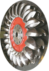
fig 8 Wheel in workshop
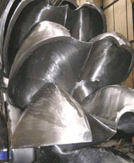
fig 9 View detail of buckets
As it is well known, Pelton turbines work in presence of big heads, therefore also the conduits must be carefully checked and inspected by means of the usual quality investigation methods, in particular using the X ray to verify the welding of big thickness shells. The following figure shows in a schematic way the altimeter trend of the connection piping and subsequent penstock.

fig 10
Just for curiosity, note the photographs (fig 11 and 12) of one wooden penstock with metal rings
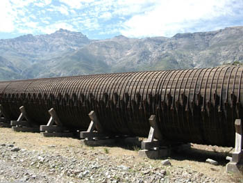
fig 11
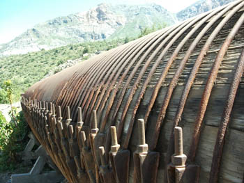
fig 12
Fig 13 shows the wheel, which external diameter is of 4.4 m, with the respective shaft and in fig 14 note the six nozzles and, on the back, the spherical valve of the S. Giacomo sul Vomano (Riva Hydroart) powerplant with the following characteristics:

fig 13

fig 14
One of the most delicate component, easily subject to wearing, is the needle. Fig 15 shows one worn needle belonging to the turbine of Fig 16
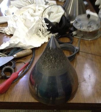
fig 15 Pelton needle
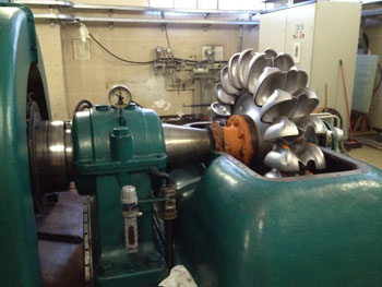
fig 16 Pelton under maintenance
Fig 17 è shows horizontal Pelton turbine section, and in Fig 18 shows vertical Pelton turbine in workshop

fig 17

fig 18

fig 19

fig 20