VALVES
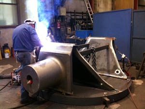
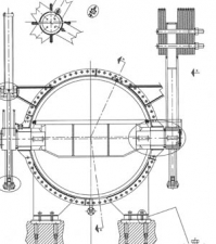
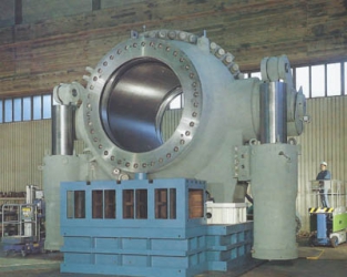
In general, hydroelectric powerplants are equipped with two types of valves, called machine valves because they control the flow before the water enters the spiral casing. Their use depends on the head and the Butterfly valves (fig 1) are usually adopted for heads not exceeding 300 m. Beyond this value, the plants are provided with Spherical valves (fig 2).
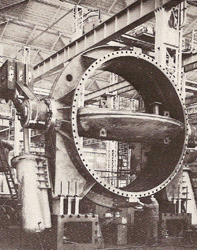
Fig 1
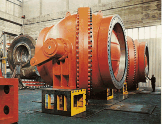
Fig 2
BUTTERFLY VALVES
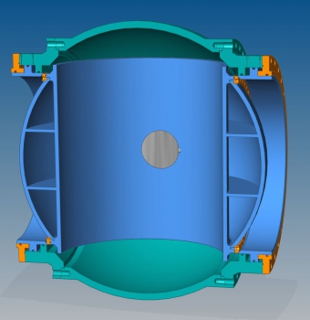
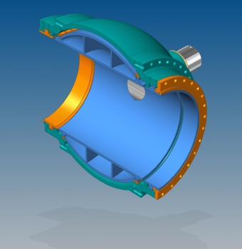
They are of simple manufacture and present head losses higher than those of Spherical valves because of the presence of the central disk. For valves which passage diameter exceeds 1.5 m, we use shaped disks (fig. 3, 4) that have the double purpose to stiff mechanically the disk and reduce the head losses. The sealing between disk and body is generally of rubber, but often the mechanical sealing is preferred in order to reduce the leaking and have more specific pressure between the parts that are in touch; this solution is preferred in presence of the highest heads. The disk opening that allows the water passage is performed by means of an oil pressure controlled servomotor, while the closure is very often controlled by means of counterweights that grant more safety. The disk trunnions rotate inside self-lubricating bushings, even if the forced grease lubrication is still used for many powerplants. The use of self-lubricating materials presents the double advantage to prevent the dispersion of polluting material in the environment and to be easily replaced. It is a good practice to dimension the trunnions and the relevant bushings so that the specific pressure remains low in order to permit longer operating times and to counteract without damage the unavoidable vibrations that take place during the operations.
SPHERICAL VALVES ROTATIVE
Spherical valves are generally used when the available head exceeds 300 m or anyway when the purpose is to limit us much as possible the head losses before the flow enters in touch with the runner, obviously to improve the global efficiency of the hydraulic machine. The valve can be represented as two balls, one fixed and the other movable inside it.
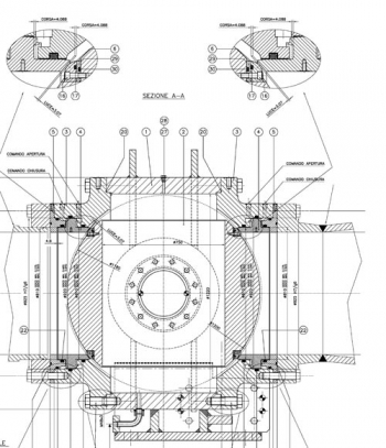
The perfect sealing, when the valve is closed, is obtained by means of various solutions, one of the most commonly adopted is schematically shown in (fig. 6, 7a, 7b). This consists of one ring of metal that, when the spherical valve is closed, approaches the movable ball resting against a specific seat of stainless steel assuring in this way the sealing. The motion of the movable ring is performed by using water under pressure taken directly from the conduit and suitably filtered. It is also possible to use oil supplied by a special system but from the ecological point of view it is absolutely inadvisable. Often the valve is equipped with two sealing rings: the upstream one is used for quick maintenance operations and is constantly not in touch. It is generally moved manually. Also this type of valves are mostly provided with self-lubricating bushings in spite of the fact that their use implies high specific pressures on the trunnions. A generous dimensioning of these trunnions with respect to what would be obtained in case of use of grease for example, will allow keeping the specific pressures within acceptable values and above all will allow avoiding the use of fluids that would contaminate the water.
