OIL SYSTEM
ACCUMULATING AND PUMPING UNIT
OIL SYSTEM To make the water flowing with its energy towards the runner of the different turbines, it is necessary that the regulation and control devices may be moved and checked. Typically we make reference to the Pelton nozzles and deflectors, to the Francis and Kaplan guide vanes, to the runner blades and to all other important components. Well all this is managed by the Accumulating and Pumping Unit. It is a tank containing oil that is put into circulation and under pressure by suitable pumps that also feed a reservoir kept constantly under pressure containing two types of fluids: oil-air or oil-nitrogen. The air is kept under pressure by a special compressor and is directly in touch with the oil, while the nitrogen under pressure is contained in suitable pre-loaded pockets or in accumulating tanks with piston that separate the two fluids. The pressures do not exceed 60 bar for the air-oil while they may easily exceed 100 bar for the oil-nitrogen. The hydraulic diagram (P&I) that shows the connection of any kind of valves, pipes, servomotors and all other components to the Accumulating and Pumping Unit is quite complicated and its explanation or comment goes beyond the purpose of these simple considerations. The accumulating and pumping unit puts at disposal all the work requested to allow the above mentioned devices to move. Generally, we can write:
 [Nm]
[Nm]
where L= regulation work Ds = servomotor diameter p= oil pressure s= servomotor stroke.
In the fig (1) we can see the unit (brown) on which the electropumps have been fitted, the air-oil storage tank and, at the bottom on the left, the servomotor. In the fig (2) the unit at the workshop.
Fig 1
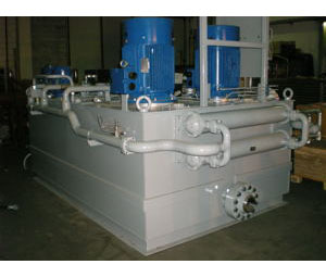
Fig 2